
Entity Relationship Modeling (ER Modeling) is a visual method used to design and structure databases effectively. It is a high-level conceptual data model that highlights the data elements and their relationships within a system. ER models help represent real-world objects and how they interact in a database system.
What is an Entity?
An Entity refers to a distinct object or thing in the real world that can be identified and separated from its surroundings. For instance, every employee in an organization is considered a unique entity. Key characteristics of entities include:
- Set of Properties: Each entity is defined by a group of attributes or properties.
- Values for Properties: Properties can have values, which describe the entity in more detail.
Example: Employee Entity
Consider an employee working in an organization. For instance, Peter, a programmer at Microsoft, represents an entity. Peter can have several properties such as:
- Attributes: Name, Age, Height, Weight, etc.
- Values: These attributes will hold specific data, like Peter’s age being 30 or his height being 6 feet.
While some attributes, like age, typically have a single value, others, like phone numbers, can hold multiple values. For example, Peter’s “Phone Numbers” property may include both his personal and work contact numbers.
Understanding Relationships Between Entities
Entities are not isolated; they often have relationships with each other. For example, if each Microsoft programmer is assigned a computer, Peter’s computer becomes another entity. The relationship here is mutual:
- Peter (Employee) uses Computer (Entity)
- The same Computer is used by Peter
This interaction showcases a relationship between the two entities.
How ER Modeling Helps
ER Modeling enables you to visually map out entities, their attributes, and their relationships. This clear representation ensures that database structures align with real-world scenarios, making them easier to understand, design, and implement.
By modeling entities and relationships, developers can create robust and efficient databases tailored to specific system requirements.
Comprehensive Guide to the Enhanced Entity-Relationship (EER) Model
The Enhanced Entity-Relationship (EER) Model is an advanced data modeling approach that extends the traditional Entity-Relationship (ER) model. This high-level framework introduces additional capabilities to handle the complexity of modern database systems, making it a preferred choice for detailed database design.
EER modeling was developed to address the challenges of representing intricate data relationships and structures in large-scale databases. By leveraging its advanced features, database architects can create more accurate and expressive models tailored to specific project needs.
A key feature of the EER model is its use of UML (Unified Modeling Language) notation. UML is a versatile and widely adopted general-purpose modeling language, primarily used for designing object-oriented systems. In EER modeling, entities are depicted as class diagrams, while relationships are visualized as associations between these entities. This approach ensures clarity and consistency in representing complex systems.
Why Choose ER Modeling Over Direct Database Design?
When designing a database, it may seem tempting to skip ER modeling and dive straight into creating tables, relationships, and database objects. However, one critical challenge in database design is bridging the gap between how designers, developers, and end-users perceive data and its usage. Without a clear, shared understanding, the result can be a database system that fails to meet user requirements.
Benefits of ER Modeling
Effective communication between stakeholders—both technical and non-technical—is essential for designing systems that fulfill user needs. Entity-Relationship (ER) models serve as a powerful communication tool, providing a visual representation of the data structure that is easy for all stakeholders to understand. Here’s why ER modeling is indispensable:
Bridging the Communication Gap
ER diagrams simplify complex data relationships, making it easier for non-technical users to participate in the design process. This ensures that the database aligns with business requirements.Improved Productivity
ER diagrams can be effortlessly translated into relational tables, reducing the time and effort required during the database implementation phase.Error Prevention
By visualizing data and its relationships early on, ER modeling helps identify potential design flaws, avoiding costly errors later in development.
Exploring Key Entities in the “MyFlix” Library Database
When designing the Entity-Relationship (ER) diagram for the “MyFlix” library, identifying the core entities is crucial to building a well-structured database. Below are the key entities that form the backbone of the system:
Members
This entity captures all essential information about the library members, including personal details and membership status.Movies
The “Movies” entity stores comprehensive information about the films in the library, such as titles, release dates, and other relevant details.Categories
Categories organize movies into specific genres, such as Drama, Action, and Epic. This structure allows users to easily browse and discover content based on their preferences.Movie Rentals
This entity tracks all transactions related to movie rentals, including which member rented a particular movie and the rental duration.Payments
Payments record all financial transactions made by members, ensuring proper tracking of fees, penalties, and membership payments.
These entities work together to streamline operations, maintain accurate data, and enhance the user experience within the “MyFlix” system. By structuring your database around these elements, you ensure a seamless and efficient flow of information.
Exploring Entity Relationships in Relational Databases
Understanding the Interactions Between Members and Movies
In a relational database, the connection between members and movies is as follows:
- A member can rent multiple movies within a given period.
- A movie can be rented by multiple members during the same period.
This scenario demonstrates a many-to-many relationship between the two entities. However, relational databases do not natively support many-to-many relationships. To resolve this, a junction entity is introduced. In this case, the MovieRentals entity serves this role, establishing:
- A one-to-many relationship with the
Memberstable. - A one-to-many relationship with the
Moviestable.
Understanding Movies and Categories Relationships
The interaction between movies and categories is defined as:
- Each movie belongs to a single category.
- A category can contain multiple movies.
From this, we deduce that the relationship between the Categories and Movies entities is one-to-many.
Exploring Members and Payments Relationships
The relationship between members and payments can be summarized as:
- A member is associated with one account.
- A member can make multiple payments.
This indicates a one-to-many relationship between the Members and Payments entities.
Creating an EER Model with MySQL Workbench
To design the Entity-Relationship (ER) model in MySQL Workbench, follow these steps:
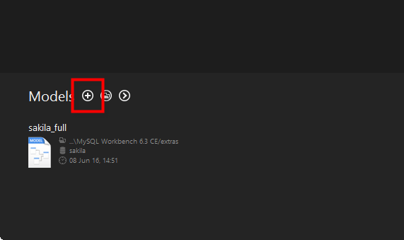
- Open MySQL Workbench and click the “+” button to create a new model.
- Design and map entities such as
Members,Movies,Categories,Payments, andMovieRentals. - Define the relationships and constraints between the entities as per the scenarios described above.
This approach ensures your database structure supports accurate and efficient data management for the specified relationships.
In the MySQL workbench , Click – “+” Button
Double click on Add Diagram button to open the workspace for ER diagrams.
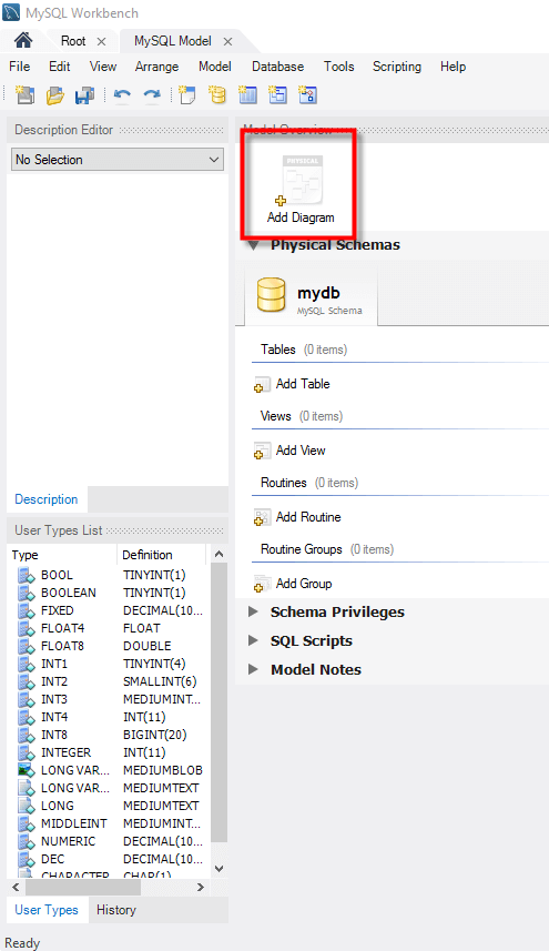
Following window appears
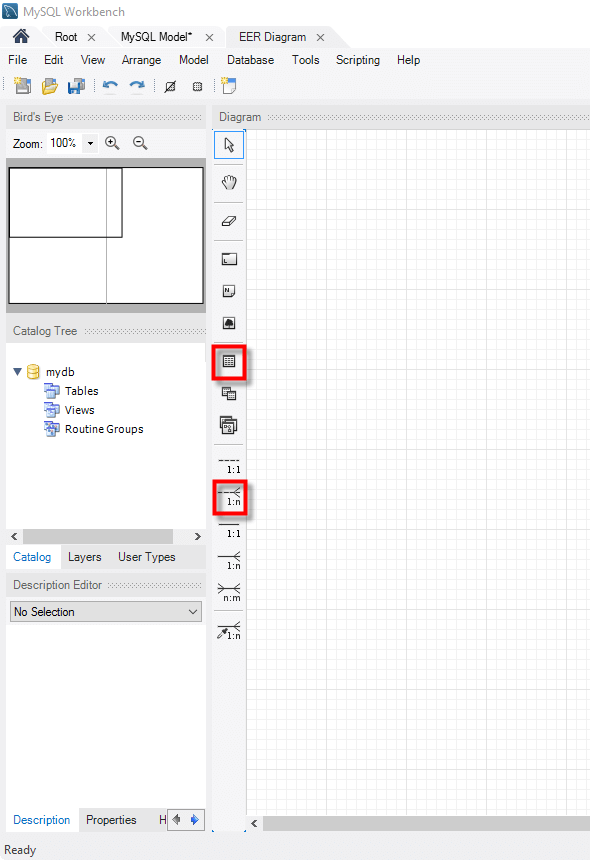
Let’s look at the two objects that we will work with.
 The table object allows us to create entities and define the attributes associated with the particular entity.
 The place relationship button allows us to define relationships between entities.
The members’ entity will have the following attributes
- Membership number
- Full names
- Gender
- Date of birth
- Physical address
- Postal address
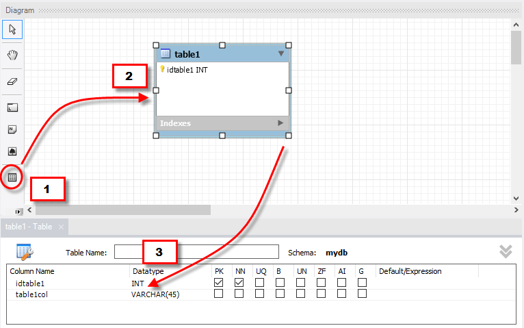
Let’s now create the members table
1.Drag the table object from the tools panel
2.Drop it in the workspace area. An entity named table 1 appears
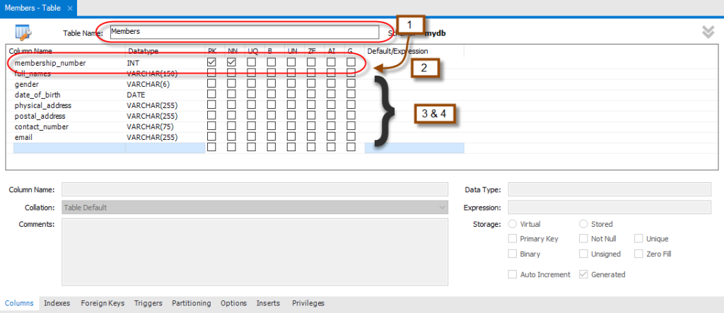
3.Double click on it. The properties window shown below appears
Next ,
- Change table 1 to Members
- Edit the default idtable1 to membership_number
- Click on the next line to add the next field
- Do the same for all the attributes identified in members’ entity.
Your properties window should now look like this.
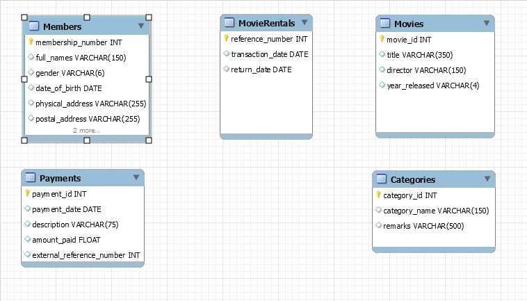
Repeat the above steps for all the identified entities.
Your diagram workspace should now look like the one shown below.
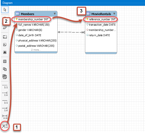
Lets create relationship between Members and Movie Rentals
- Select the place relationship using existing columns too
- Click on membership_number in the Members table
- Click on reference_number in the MovieRentals table
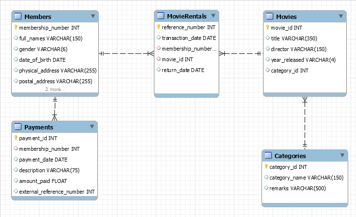
Repeat above steps for other relationships. Your ER diagram should now look like this –
Understanding ER Diagrams: A Crucial Tool for Database Design and Communication
Entity-Relationship (ER) diagrams are fundamental tools in the database design process. They provide a clear visual representation of entities (real-world objects or concepts) and their relationships, making them an effective bridge for communication between technical and non-technical stakeholders.
Entities can represent either tangible objects, like customers, or abstract concepts, such as sales orders. Each entity in an ER diagram must have a unique name to maintain clarity and prevent ambiguity.
Beyond identifying entities, ER models help database designers map out the relationships between these entities, ensuring the database structure is logical, efficient, and aligned with business needs. By leveraging ER diagrams, teams can streamline collaboration and reduce misunderstandings, paving the way for robust and well-organized databases.


Leave a Reply